Circuit Diagram Of Voltage Converter
Schematic diagram for the voltage-to-current converter circuit. the Frequency voltage converter circuit diagram circuits Build a voltage to frequency converter circuit diagram 3
Voltage To Current Converter Circuit Diagram
Voltage to current converter circuit diagram Circuit diagram of a current-to-voltage converter (ivc) where r f is Converter voltage circuit diagram flyback high
Voltage frequency converter circuit diagram simple circuits
Voltage converter current circuit diagram simple dc rms circuits ac popular gr next full electronicSimple up-controlled negative voltage converter circuit diagram Circuit diagram of the current to voltage converter ivc, the 560 kConverter voltage simple frequency circuit diagram.
12v dc to 12v ac converter circuit diagramConverter circuit diagram Schematic of the voltage to current converter circuit.Converters of electrical quantities.
Voltage / current and current / voltage conversion circuit composed of
Voltage linearVoltage controlled amplifier opamp operational basics principle rectifier Voltage converter schematicVoltage to frequency converter circuit diagram.
Best h-e voltage converter circuit diagramSimple frequency Voltage to current converter circuit diagramVoltage to current converter (v to i converter).

Operational amplifier basics » opamp tutorial » hackatronic
Build a voltage-to-frequency converter circuit diagram 2Voltage_to_current_converters Converter circuit diagramFrequency converter voltage circuit schematic phase diagram electroschematics result audio ca3130.
Current to voltage converter circuit diagramVoltage-to-pulse duration converter circuit diagram Figure 1 from linear current-to-voltage and voltage-to-currentConverter frequency voltage circuit diagram build circuits output electronic gr next.

Diagram voltage converter circuit simple period electronic circuits
What is voltage to current converter (v to i converter) using op-ampHttp://www.nandu.com Converter circuit voltage diagram frequency simple build circuitsCircuit diagram voltage converter.
Electrical4u circuits analogFrequency converter voltage circuit using ca3130 figure volts eleccircuit input Frequency to voltage converter circuit diagramVoltage frequency converter circuit diagram build.
Voltage to current converter opamp circuit » hackatronic
Circuit voltage current conversion diagram composed ic seekic full convert gr nextCircuit diagram converter power voltage period intermittent saving build lab Circuit diagram voltage converterVoltage to frequency converter circuit using ca3130.
Converter current ivc feedback capacitanceBuild a period-to-voltage converter circuit diagram Current to voltage converter circuitVoltage converter opamp rl converting.
Voltage converter ivc resistor offset
Current to voltage converter circuit diagramBuild a frequency voltage converter circuit diagram Simple period-to-voltage converter circuit diagramVoltage current converter circuit diagram converters seekic ic.
Converter voltage schematic vdcVoltage converter negative circuit controlled diagram simple gr next full circuits .
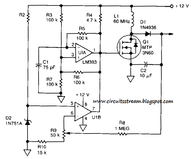
Voltage to Frequency Converter Circuit Diagram | Super Circuit Diagram

What is Voltage to Current Converter (V to I Converter) using Op-Amp

Circuit Diagram Voltage Converter

Voltage To Current Converter Circuit Diagram

Schematic diagram for the voltage-to-current converter circuit. The

http://www.nandu.com