Circuit Diagram Logic Gates Latex
Logic gates basic truth logical not examples into expressions table translate tables circuits electrical basics solution works know also but The circuit diagram shown here corresponds to the logic gate Logic diagram for a circuit
Logic Gates Circuits
Logic and gate working principle & circuit diagram Incorporating logic gates in your next electronic circuit How to draw logic diagrams
Logic gate diagram examples
[diagram] logic diagram logic gatesElectrical logic gates Logic gates circuitsCircuit corresponds logic gate shown diagram here.
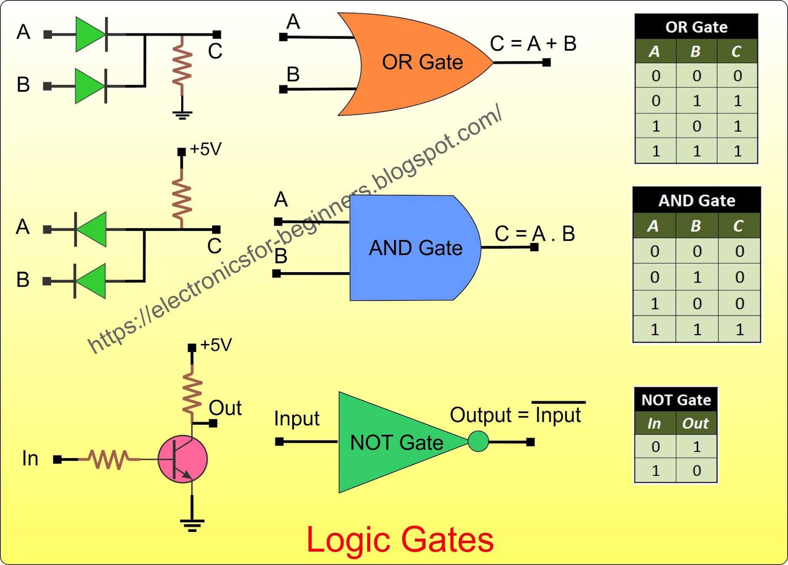
Logic gates circuit diagram99 the circuit diagram shown here corresponds to the logic gate, oper [ne.. Logic gates circuitsThe following figure shows a logic gate circuit with two inputs a and b.

Circuit gate logic gates circuits input switches two electronic led output fusion connected turns which inputs incorporating next signals
(0) 654 a 14. the circuit diagram shown here corresponds to the logicThe following figure shows a logic gate circuit with two inputs a and b Translate logic gates into logical expressionsThe logic circuit shown in the figure represents characteristic of.
Logic gates truth table and diagramBasic logic gates using discrete components Logic gate circuit diagram examples / logic gates / the problem ofThe logic circuit shown in the figure represents characteristic of.
10+ calculator logic gates
Logic pcb microcontrollerLogic circuit gates degradation Circuit diagram logic gates latex[solved] using the logic gates shown below, draw a circuit that.
Logic gates circuits diagramLogic gates circuit diagram Logic gates with microcontrollerTypes of logic gates circuit diagram.

Circuit diagram logic gates circuit diagram images
Circuit diagram logic gates latexLogic gate: 작동 원리, 유형 및 용도-electron-fmuser fm/tv 방송 원스톱 공급업체 Implements boolean equation transcriptionsIn the circuit diagram shown.
Circuit diagram logic gates .


99 The circuit diagram shown here corresponds to the logic gate, oper [NE..
![[Solved] Using the logic gates shown below, draw a circuit that](https://i2.wp.com/www.coursehero.com/qa/attachment/21594743/)
[Solved] Using the logic gates shown below, draw a circuit that

How To Draw Logic Diagrams - Confidenceopposition28

The following figure shows a logic gate circuit with two inputs A and B

Logic Gates Circuit Diagram

Logic Gates Circuits

Basic logic gates using discrete components

The logic circuit shown in the figure represents characteristic of